Reverse engineering
An existing tool or part is measured from its datum faces, holes over gauge pins, and rebuilt as a 1:1 CAD model. You can then repair it, copy it or change it without guessing.
- Measurement report
- STEP
- Drawings
Engineering studioValmiera, Latvia
Reverse engineering, tool and fixture design, drawing packages and design checks. One engineer, from the first measurement to the files your toolmaker needs.
Answer within one working dayNDA on requestPrice agreed before work starts
Services
The tool is on the bench, the drawings are missing or wrong, and the line needs it back. That is the kind of work this studio is built for.
An existing tool or part is measured from its datum faces, holes over gauge pins, and rebuilt as a 1:1 CAD model. You can then repair it, copy it or change it without guessing.
Assembly tools, press fixtures, cutting dies and their rework: a new insert, a new stop, a guide that fits the new product.
Manufacturing drawings of every part with tolerances, fits, materials and hardness, a parts list and a change note per revision.
A supplier's design is checked against the product 3D: fits, clearances, stroke and tolerances, before it is approved or paid for.
The core is above. These exist because a tooling job rarely ends with the drawing: a part has to be tried, an instruction written, a check automated.
Parts designed for the printer and printed: a trial insert to check fit and handling before steel is cut, assembly jigs, holders, gauges and covers. An existing CAD model is made printable: orientation, wall thickness, supports and allowances for the process. You get the print-ready files, or the printed part itself. A print shows fit and handling; fine clearances are still proven by measurement.
Setup and operating instructions, inspection plans and one-page work instructions for the shop floor.
Programming to order, not only around CAD: web and mobile applications, shop-floor log books and dashboards, databases and reporting, embedded devices, automation scripts and integrations between the systems a factory already runs. PLC programs too: a new program written for a machine or station, or an existing one read, corrected and extended.
CAD models are taken into Blender for photoreal renders, exploded views and cycle animations, and into the browser as interactive viewers for product pages, instructions and design reviews.
Company and product websites built the way this one is: structure, text, design, rendered 3D and code from one desk. Fast on an ordinary office PC, readable on a phone, with a request form that actually reaches you, and no stock photos pretending to be your factory.
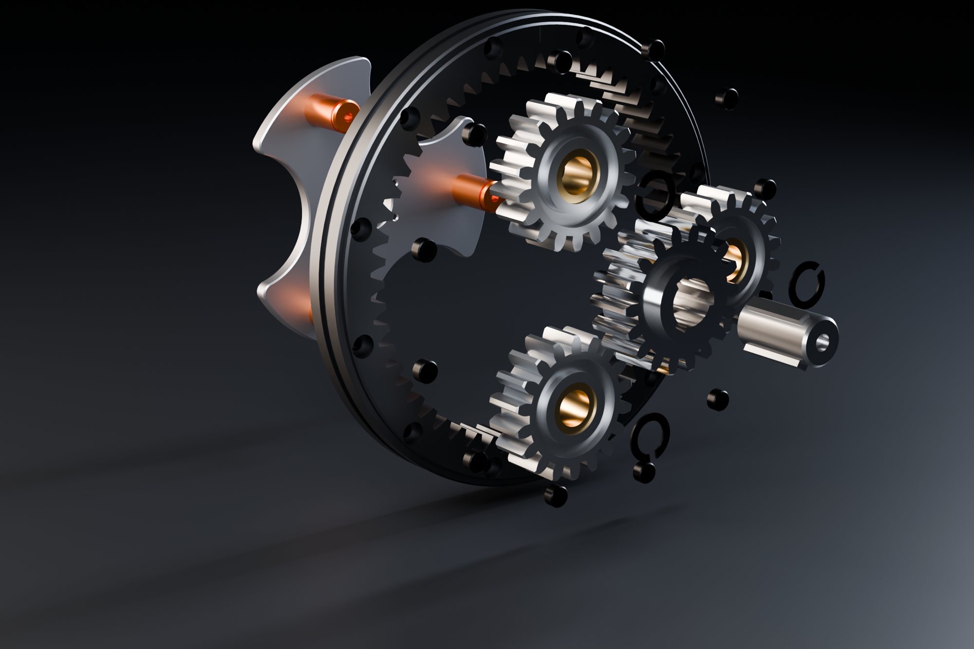
This exploded view and the drawing at the top of this section come from the same CAD model. Build the geometry once and correctly, and the parts list, the drawings, the collision check and the pictures for the manual stop contradicting each other.
Reverse engineering method
Anyone can read a caliper. The work is in knowing what to measure from, what to measure with, and which reading to trust when two of them disagree. These are the rules every part goes through here.
Two ground pins stand in the holes and take up their true axes. The caliper closes on the outside of the pins, where its jaws are flat and parallel, and reads 46.12. Half of each pin diameter comes off, and the centre distance is 39.12. Measured with the jaw tips inside the bores, the same two holes can read several hundredths differently every time.
The part is set on its reference faces and every dimension is taken from them, not chained from the previous one. Errors do not add up along the part.
Holes and centre distances over gauge pins, never with jaw tips inside a bore. Depths with a depth gauge, threads and radii with gauges, small steps with a micrometer.
Critical dimensions are taken several times and from both sides. Each reading is photographed with the scale in the frame, so any value can be traced back later.
Hole patterns must share a pitch, mirrored sides must mirror, a pin must be coaxial with its hole in the mating part. Raw readings are reconciled against these rules before they become CAD.
A worn edge is not copied as a dimension. Fits are set from the function to ISO 286, general tolerances to ISO 2768, and catalogue parts are identified by their order number instead of being redrawn.
The finished model is assembled virtually and checked for interference, and compared with 3D scan data when a scan exists. Anything assumed is marked as assumed in the report.
What you receive
Geometry studies
Client tools stay confidential, so these are study models built in-house: classic mechanisms, modelled from their equations. The wheel indexes exactly a quarter turn, the output shaft speeds up and slows down as the joint angle demands, the follower lifts by the law the cam was cut to.
A Geneva drive turns continuous rotation into exact steps. The pin enters a slot, carries the wheel a quarter turn and leaves; for the rest of the revolution the locking disc holds the wheel still.
Process
You always know which step the job is in, what is still open and what comes next.
You send what exists: the tool or part, old drawings, the product 3D, photos of the problem. We agree what the result must do.
Parts are measured, files are read and compared. Missing or contradictory data goes on a list with questions.
3D model and virtual assembly with the real product: interference, clearances, press stroke.
Manufacturing drawings with tolerances, materials and hardness, a parts list and the file formats your toolmaker uses.
You review on a tablet or PC. Every change goes into a change note with its revision letter.
The full package in one folder: STEP, DWG, PDF, change log. Support during manufacturing and the first trial.
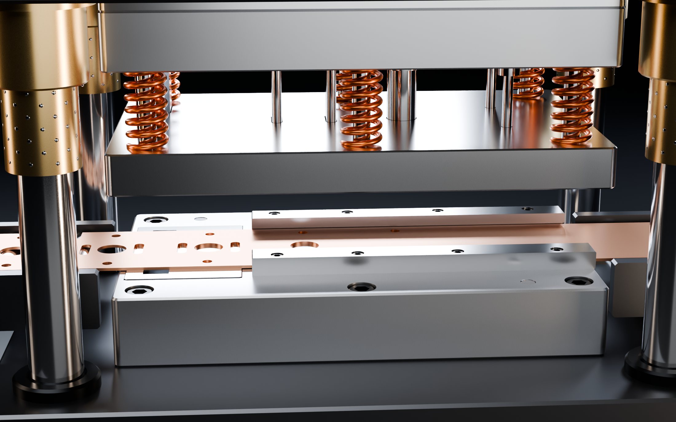
A die like the one on the first screen closes in a fraction of a second. On the way down the stripper meets the strip first, the springs compress, the punches pass through and stop a set distance into the die. Every one of those events has a stroke value, and each can be wrong by a few tenths without anyone seeing it on a drawing.
Design check
The product 3D is placed into the tool and the press stroke is run in 0.01 mm steps. Every contact is recorded: where the tool first touches the part, where a latch engages, where a hard stop sits, whether the target position is reached.
The result is a short report with sections and numbers that a toolmaker can act on.
| Stroke, mm | Event | Result |
|---|---|---|
| 11.20 | Stripper touches the part | spring travel 1.8 of 4.0 |
| 12.85 | Latch starts on the ramp | ok |
| 13.40 | Insert lands on a rib of the part | hard stop |
| 14.10 | Target position | not reached, 0.70 short |
| 14.10 – 14.45 | Window for a depth stop | stop set to 14.25 ± 0.1 |
Why TurkovLAB
What is new here is not a machine. It is the order of work: measure by rule, build one model, then let code run the tool through its stroke before anyone orders steel. This is what that changes for you.
One reading per dimension, taken where the caliper happens to fit.
From datum faces, over gauge pins, repeated and photographed.
The design is looked over on screen and judged by eye.
The press stroke is computed in 0.01 mm steps with your product inside the tool.
Measuring, design, drawings and software sit with different people and drift apart.
One engineer and one model. Every drawing, list and picture is derived from it.
A new file quietly replaces the old one.
A revision letter and a change note, every time.
They show up at the first trial, in steel.
They show up in a report, while a fix still costs an hour.
The die came to the bench for two days. It was measured from its datum faces and over gauge pins, then rebuilt as a 1:1 CAD model with a measurement report and a full drawing set. A spare can now be ordered from the files alone.
In a manual assembly tool the part did not reach its final position and jammed. The cause was found in the 3D model, the upper insert was redesigned, and two variants were printed and tried before anything was machined.
A supplier delivered tools without a part needed to assemble them. It was identified in the 3D data as a catalogue guide pillar, the parts list was corrected where it disagreed with the model, and the plant got an order number instead of a drawing it did not need.
With a plan, the open questions and what I need from you. Not an auto-reply.
A fixed price when the input is complete. An hourly rate with an estimate when it is not. No work starts before you agree.
Client tools, files and names are never shown, on this site or anywhere else. An NDA is signed before files are sent, if you need one.
Every revision has a letter and a change note. You always know what changed, when and why.
STEP, DWG, DXF, PDF and source code are yours. Nothing is locked into a format only I can open.
Questions from your toolmaker are answered during manufacturing and at the first trial.
A good fit
Better done elsewhere
About
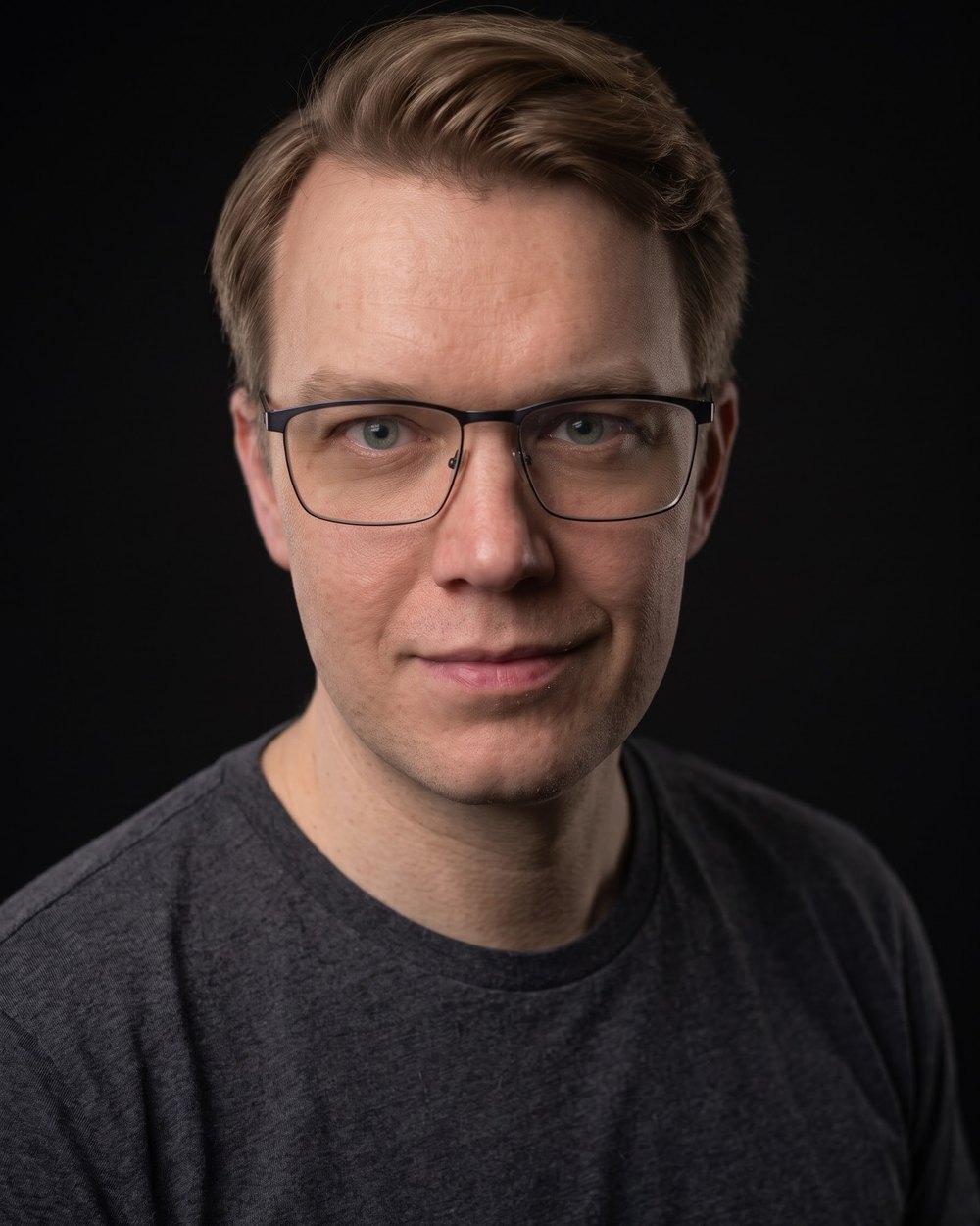
I am Oleg Turkov, the engineer behind TurkovLAB. You work with me directly, from the first message to the last revision: no account managers, no hand-offs.
I build 3D models, drawing packages and design checks for tooling and production equipment in Fusion and AutoCAD. Reverse engineering is done by the book: datum faces, gauge pins, repeated readings, and a measurement report that shows how every value was obtained.
The second half of the studio is programming. Where a check is repetitive or must be exact, I write it as code: virtual assembly of the product in the tool, stroke and interference calculations, version-to-version comparison. The same goes for stand-alone software: applications, dashboards, device firmware and integrations, in the language the job calls for. Finished models are rendered and animated in Blender. This website is part of the portfolio: its structure, text, 3D models, films and code were all made here.
Based in Valmiera, Latvia. Remote with manufacturers across Europe, on site when a tool needs measuring. Working languages: English, Latvian, Russian.
Toolbox
Questions
If yours is not here, write it into the request. A question costs nothing.
Whatever exists: the part or tool itself, old drawings, a product 3D file, photos with a ruler in the frame, a short description of the problem. Incomplete input is normal. The first thing you get back is a list of what is missing and how to close each gap.
Hand instruments capture ordinary features to a few hundredths of a millimetre, and repeated readings show how far each value can be trusted. Fits are not copied from a worn part: they are set from the function and stated on the drawing. If a feature needs tighter verification than hand measurement can give, I say so and name the right method for it.
After I have seen all the input. A complete package gets a fixed price. When data is still missing, you get an hourly rate with an honest estimate of the hours, updated as the gaps close. Either way it is agreed in writing before work starts.
No. Everything shown here is study geometry made in-house for that reason. Client work stays confidential whether or not an NDA exists, and I sign yours before you send files if you need one.
Yes. This site is the reference: one page, written and designed around what a buyer needs to decide, with 3D films rendered from real CAD models and a working request form. Yours starts with the same question: who should contact you after reading it, and what do they need to see first? You get the source code and the hosting set up in your own account.
No. You receive drawings and files your own toolmaker can quote and cut from, and I answer their questions while they do. That keeps the design independent of any one workshop.
Not necessarily. Small tools and parts can be shipped and are returned after measuring. In Latvia I can measure on site when a tool cannot leave the line. Design reviews, drawings and software are done fully remote.
It usually does. The change is written down with its effect on scope and price, you confirm it, and it gets its own revision letter and change note.
Request a quote
Three lines are enough to start. No obligation: you get a plan and a price, and decide then.
Thank you. You will get an answer with a plan and the open questions within one working day.
The request could not be delivered automatically. Your text is ready below: send it by e-mail to olturkovs@gmail.com.